工場の換気システムの役割
工場の換気システムは、新鮮な空気の供給、汚染された空気の除去、労働者の安全で快適な作業環境の確保を目的とする重要なシステムです。
換気システムが悪いとどうなるか
工場の換気システムが正常に機能しないと、時間の経過とともに工場にほこりが蓄積されます。同時に、人間の呼吸プロセスによって二酸化炭素ガスの濃度が高まり、酸素が大幅に減少します。また、工場の湿気でカビや細菌が繁殖します。ホルムアルデヒド、ウイルス、カビなどの有害排出物がどんどん蓄積され、人体に大きな害を及ぼします。工場のほこりの増加は、人体と生命に危険な病気を引き起こす危険性があります。酸素不足と相まって、人間の呼吸が困難になります。したがって、タイムリーな介入措置が必要です。
換気システムを設計する際には、次の多くの要因を考慮する必要があります。
- ほこりや煙の発生源:工場のほこりや煙の発生源は、生産プロセス、機械、装置など、さまざまなものから来ることができます。工場のほこりや煙の拡散能力も考慮する必要があります。
- 工場のレイアウト:工場のレイアウトは、工場の空気の流れに大きな影響を与えます。生産エリア、作業エリア、保管エリアなど、適切に配置して、空気の流れを良好に保つ必要があります。
- 現在の空気の流れのモデル:現在の空気の流れのモデルを研究して、ホットスポット、汚染リスクの高いエリアを特定する必要があります。
- 将来の工程変更:将来の工程変更がある場合は、これらの変更が換気システムに与える影響を考慮する必要があります。
換気システムを設計する手順
換気システムの設計は、次の5つの手順で行います。
- 現地コンサルティング:現地コンサルティングを行い、顧客の課題と目標をより深く理解します。
- データ収集:ほこりや煙の発生源、工場のレイアウト、現在の空気の流れのモデルなど、データを収集します。
- モデリング:3Dモデルを作成します。顧客の施設、空気の流れに影響を与える要因を含みます。
- システム設計:モデリングの結果と顧客の要件に基づいて、最適な換気システムを設計します。
- 最終評価と分析:換気システムを評価して分析します。実装後、システムが正常に動作していることを確認します。
効果的な換気システムのメリット
効果的な換気システムは、工場にとって多くのメリットをもたらします。
- 労働者の安全で快適な作業環境を確保します。
- 大気汚染を削減し、呼吸器疾患を予防します。
- 労働生産性を向上させます。
- コストを節約します。
したがって、工場にとって、効果的な換気システムの設計と設置は非常に重要です。
| Before | 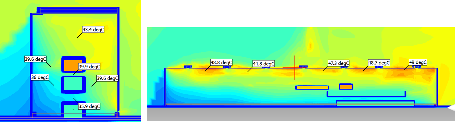 |
| After | 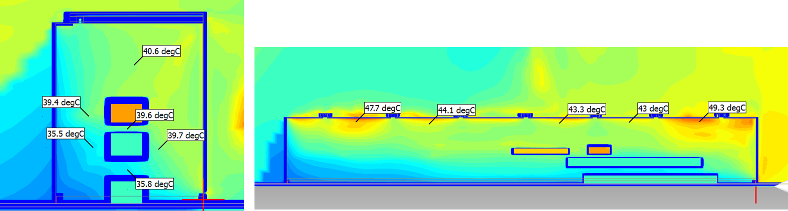 |
Air movement inside the factory
| Before |  |
| After |  |
---------------------------------------------